How to Know if You Overheated a Circuit Breaker
An electrician had a customer with a very mutual trouble—an overheated electrical panel. What fabricated the situation somewhat unusual was the fact that the overheating didn't result from whatsoever of the usual causes.
The electrician was chosen in to troubleshoot an electric panel with 42 circuit breakers that supplied ability to dozens of servers and other non-linear loads. The Information technology tech at the client site noticed that the face of the 225A main circuit breaker, which was supposed to be white, was noticeably yellow. When he felt the face up he found that it was non only discolored—information technology was seriously warm to the bear on.
Although at that place had been no outages, the resources powered through this console are mission critical, so the client couldn't beget to wait until things went bad to address the problem.
Troubleshooting with the power on
Since even a planned shutdown would take been very hard to schedule, all troubleshooting was washed with the power on. In an initial survey of the surround, the electrician noted that the neutral conductor consisted of 2 4/0 conductors, an oversized neutral commonly plant in console boards that serve non-linear loads. That told him the system was designed properly.
His next task was to bring out his Fluke 1587 Insulation Multimeter to mensurate the phase-to-stage and phase-to-neutral voltage on the line side of the 225A main circuit breaker. He was looking for any anomalies that could indicate to a problem. Those measurements all were well within the normal range—nothing too high or too low.
Side by side he looked at the current draw on each of the incoming phase conductors with the Fluke 376 Clamp Meter and plant that the current was well below 225A on all three phases—ranging from 108.9A to 130.3A. Considering the console powered not-linear loads, the next logical step was to look for current harmonics. The electrician clamped the 376 on the neutral usher and plant the electric current to exist quite low—but 38.9A. If harmonics were causing a trouble, the current on the neutral would have been equal to or higher than 1 of the phase currents.
Ruling out harmonics
What about the loads served past the panel? Perchance there were voltage harmonics there? This time the electrician brought out his Fluke 434 Energy Analyzer to check the harmonic content of the loads served by the panel in question. The harmonic content was consistent with the blazon of loads served. The voltage was practiced and there wasn't a lot of extra high electric current or harmonics; once again he hit a dead terminate.
But he wasn't finished. Side by side he recorded the voltage drop across the line and load side phase conductors of the master circuit breaker (See Table i). A loose or bad connexion or an internal problem with the excursion could produce a big voltage drop—something greater than 100 millivolts.
| Measurements | |
|---|---|
| A phase: 51.one millivolts | A phase: 122.9 amps |
| B stage: 41.half dozen millivolts | B phase: 108.nine amps |
| C phase: 137.1 millivolts | C stage: 130.3 amps |

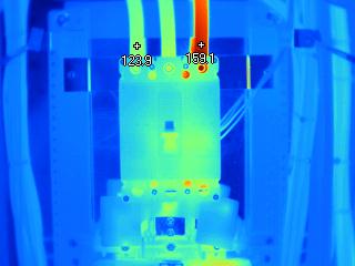
The voltages measured across the "A" and "B" phases were well within range. Still, when he got to the "C" phase the 137 mV measurement made it pretty obvious where the heat was coming from. Since the problem withal didn't warrant a shutdown, the electrician brought out his Fluke Thermal Imager, which not surprisingly showed the C phase was significantly warmer than the A and B phases (Encounter Figure 1).
At the top of the excursion breaker the wire was very warm and grew libation as the camera moved farther manner from the circuit breaker. This indicates that the problem was nigh likely at the lug or where the lug connects to the circuit billow.
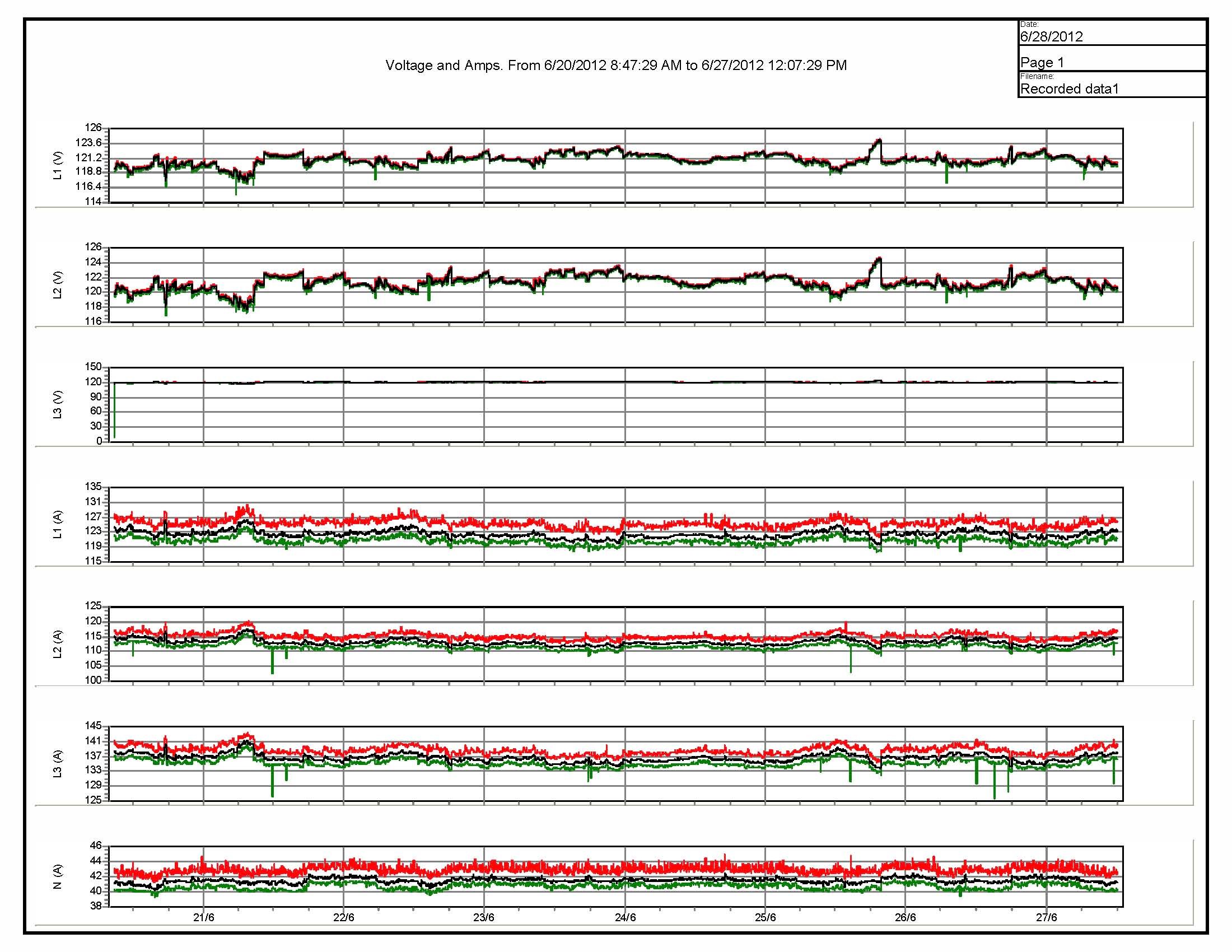
Before leaving the site, the electrician attached the Fluke 1735 Three-Stage Power Logger to the conductors feeding the 225A chief circuit breaker and left it for a calendar week to measure out current. That didn't show any anomalies with the electric current. (See Effigy 2)
Because the troubleshooting isolated the location of the problem but didn't pinpoint the exact cause, the customer and electrical consultants decided to supersede the entire guts of the panel—including all of the excursion breakers—and pull new conductors. "We're going to that extent because the cost of downwards fourth dimension and criticality of the organisation are and then significant that the customer wants it fixed. They don't want to have to adjust another outage anytime shortly," the electrician explains.
The resolution
Later on on the customer found a window of opportunity to shut down the console and supersede it. The electric consultants weren't taking whatever chances, though. Before the panel shutdown was scheduled, the new console interior—complete with branch circuit breakers and primary circuit breaker—was sent to an contained testing company. The testing company torqued all the internal connections to specifications and performed a digital depression resistance ohmmeter test to verify the integrity of the internal connections.
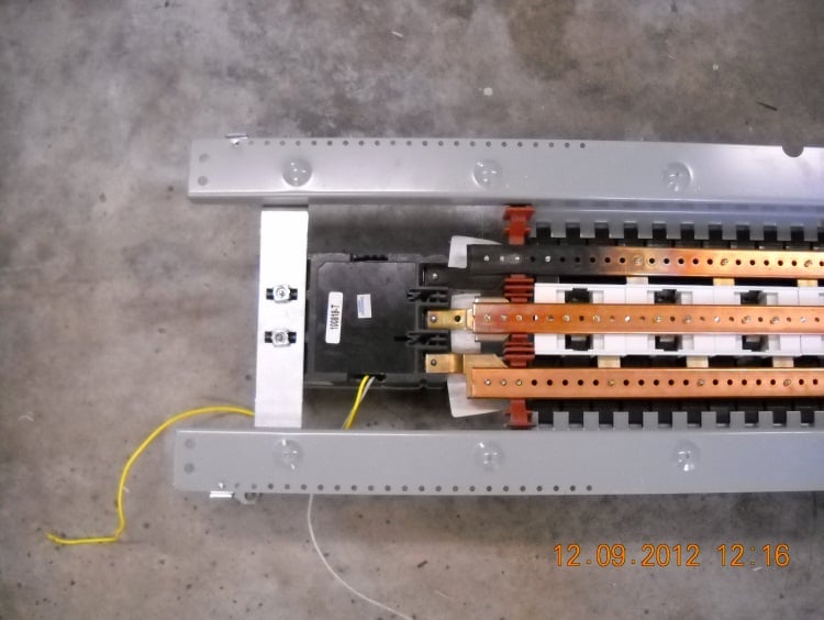
With a clean bill of health on the new panel, the consultants went to work. They de-energized the onetime panel, disconnected all the conductors, and removed the guts. At that betoken they did a visual examination and found that there were signs of severe overheating at the point where the A stage bus connects to the main circuit breaker. [See Figure three]
Next the electricians installed new interior phase bussing, co-operative excursion breakers, main circuit breaker, and stage conductors, and reconnected all the conductors. Afterward re-energizing the panel, they tested it to verify that the new panel was working as specified. Using the Fluke 1587 Insulation Multimeter they took a series of voltage measurements including the voltage drop across the line and load side of the chief circuit breaker, which showed the post-obit voltage drops:
- A phase: l.4 millivolts
- B phase: 48.8 millivolts
- C stage: 41.iv millivolts
These measurements were well within the normal range so next they measured the amp load on the phase conductors with the Fluke 376 Clamp Meter:
- A phase: 144.ane amps
- B stage: 133.7 amps
- C stage: 132.6 amps
Those readings were also inside the adequate 80 percent rating requirement.
Finally, they scanned the stage conductors of the main circuit breaker nether load using a Fluke Thermal Imager. The scan showed balanced loads across all 3 phases.
Going forward
Although the measurements showed that the new panel is operation within the fourscore percent load rating, the consultants await it to arroyo the lxxx percent threshold soon. As the load increases so does the heat, and then they recommended that the customer monitor the situation and plan to install a new power feeder in the not-besides-distant future.
torreshavocapiente.blogspot.com
Source: https://www.fluke.com/en-us/learn/blog/power-quality/troubleshooting-electrical-panel-overheating-problem
0 Response to "How to Know if You Overheated a Circuit Breaker"
Enregistrer un commentaire